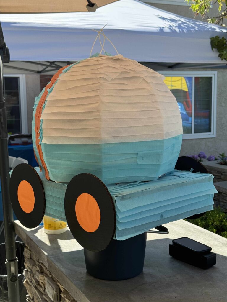
Every year I like to make a piñata for my kids’ birthday parties. Not only does it save money, but it’s also a great way to reuse the extra cardboard around the house. I use my laser cutter to cut cardboard pieces modeled with OpenSCAD. If you’re unfamiliar with OpenSCAD, it’s a great open source tool that allows you to design 3D models via a programming language.
This year my son wanted a Blippi themed birthday party, so I wanted to make a piñata of the BlippiMobile. This ended up being the largest piñata I’ve made yet, and as such ran into a problem due to the 20″ x 12″ size limit of my laser cutter. Since certain pieces I designed required cardboard pieces larger than that, I ultimately decided to break each large piece up and design them with “puzzle connector” pieces to assemble after being cut out. This sent me down a fun little trigonometry problem to calculate how to make the rounded trapezoidal shape of a puzzle connector.
Defining The Variables
OpenSCAD allows us to define modules so that we can keep reusing them. Since I anticipate making more large piñatas in the future, I wanted to design this puzzle connector piece in a way that allowed me to change the dimensions of it in the future.
First, let’s take a look at what I ultimately wanted to design:
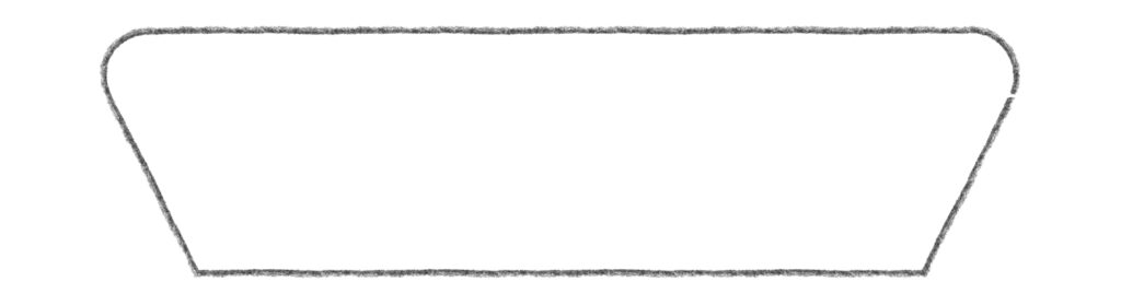
It’s a pretty basic shape, but for reusability I wanted to be able to dynamically specify the width of the piece, the height of the piece, and the corner radius value to control the “roundness.”
At its core, this shape is essentially a trapezoid whose acute angles are rounded. To get the rounded corners, we can first imagine inscribing circles into the acute angles of a trapezoid like so:
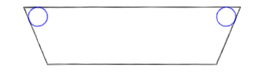
The “corner radius” variable will control the radius of these circles. Next we can change the trapezoid into a polygon clipping out the acute angles where the circles are. This can be achieved by finding the points where the circle touches the lines of the trapezoid and connecting them together directly like so:
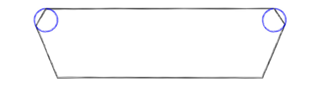
Now this modified polygon and the two circles can be joined via a boolean union operation to create the final shape.
Starting the OpenSCAD Project
OpenSCAD’s programming language is specific to OpenSCAD, but it’s very reminiscent of other scripting languages like JavaScript. The first thing we sdo is define a module with the three variables we’ve identified:
module PuzzlePieceConnector(width, height, corner_radius) {

}
Calculating The Top Angles
The bulk of the calculations needed are to determine the individual points of the polygon above. Though we’ve identified our three width, the height, and the corner radius variables, the one important variable that isn’t defined is the relationship between the horizontal lines of the trapezoid (the top and bottom line). The width variable only defines the width of the entire piece, not the width of the shorter line of the trapezoid. For simplicity, I decided to make the bottom horizontal line 75% of the specified width.
From this point forward, we’re going to focus on just the left side of the polygon, since once we have the values there, we can copy them for the other side.
The first value we can calculate is the angle of the top left corner. We can do this by drawing a vertical line from the bottom left corner up to the top line so that it is perpendicular to the top line (and therefore a right angle).
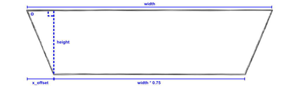
This forms a right triangle whose height is the same as the specified height variable and whose width is currently specified with an x_offset variable name. The value of x_offset is equal to the difference between the top horizontal line width and the bottom horizontal line width, all divided by 2 (since there’s technically an x_offset value on the right side of the trapezoid too). Since the bottom line is equal to the width multiplied by 0.75, that means the difference between the top line and the bottom line is also equal to the width multiplied by 0.25 (width - (0.75 * width) = 0.25 * width). Let’s update our OpenSCAD code with the new x_offset variable:
module PuzzlePieceConnector(width, height, corner_radius) {
    x_offset = (width * 0.25) / 2;
}
We now have the right triangle’s width and height, which means we can calculate the top left corner angle (marked with a theta, or Θ). To do this, we can bust out the old SOH-CAH-TOA from high school trigonometry class. Since we have the adjacent and opposite values to the angle, we need to use the TOA part of SOH-CAH-TOA, a.k.a. the tangent.
tan(Θ) = height / x_offset;
// To get just the angle, we need the inverse tangent, or arctangent:
Θ = arctan(height / x_offset);
Let’s add it to our module:
module PuzzlePieceConnector(width, height, corner_radius) {
    x_offset = (width * 0.25) / 2;
    theta = atan(height / x_offset);
}
Calculating The Polygon
Now that we have the top left angle, let’s zoom in and see what other right triangles can help us.
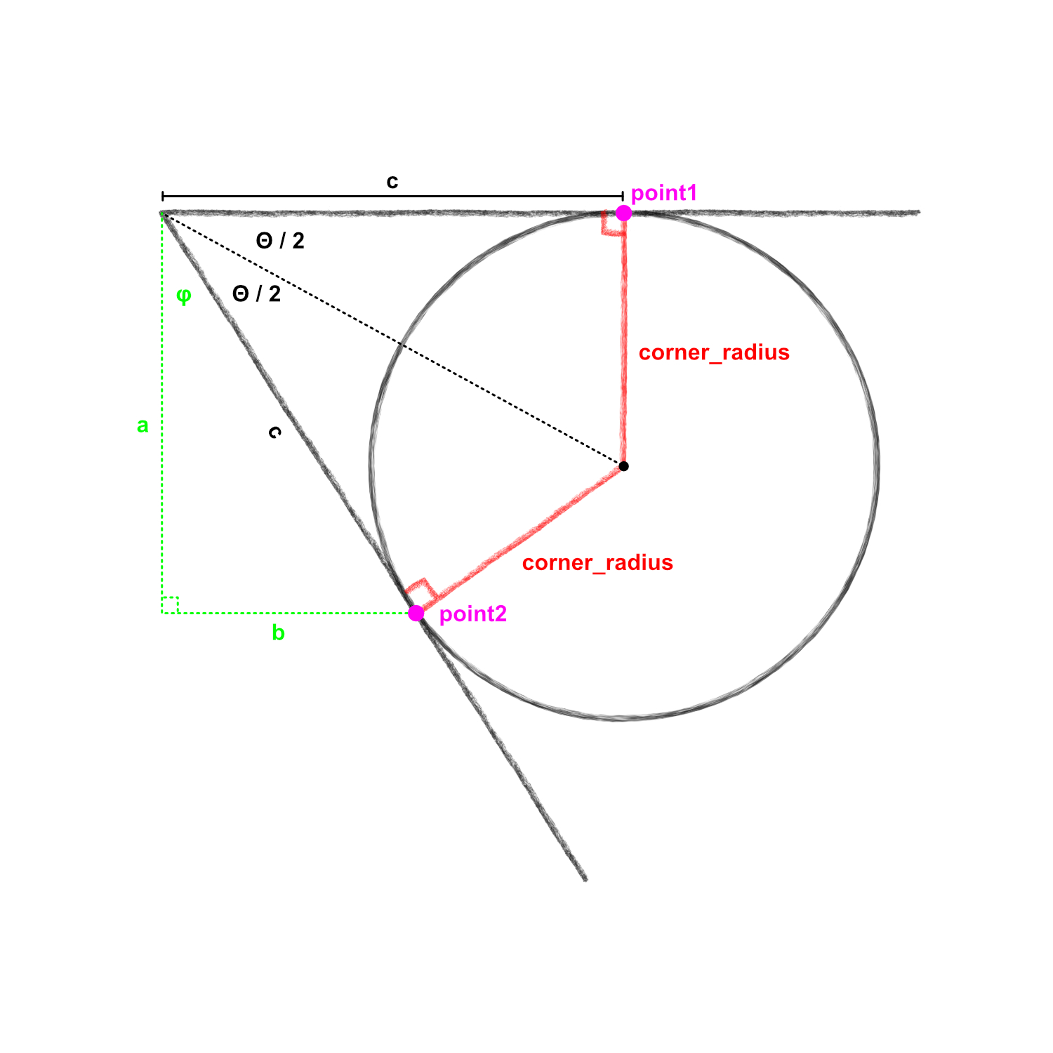
In this zoomed in picture of the top left corner, we can see the inscribed circle. To make the polygon we’re interested in, we need to find the x and y coordinates of the pink points marked point1 and point2.
A quick note: coordinate systems in programming languages and systems can vary. Sometimes a positive y value moves upward, and in other cases a positive y value moves something downwards. In OpenSCAD, a positive y value goes upward whereas negative y values move downward.
Because the circle is inscribed in the corner of the trapezoid, it only touches the lines of the trapezoid at two points (point1 and point2). That means that these 2 lines are tangent to the circle and therefore perpendicular to the radius of the circle, creating a right angle (drawn in red in the image). If we then draw another line from the center of the circle to the corner of the trapezoid, we create 2 right triangles that bisect the angle θ we previously calculated.
Calculating Point1
We can see that the x coordinate of point1 is equivalent to the value marked as c and the y coordinate is equal to the height value of the trapezoid. So the only value we need to calculate for point2 is c.
For this right triangle, we know angle on the left side (Θ/2) as well as the opposite side length (corner_radius). The value we’re interested in is the adjacent side (c). So with opposite and adjacent values, we again need the tangent for our calculation. Since the tangent of our angle equals the opposite over the adjacent, we can cross multiply the values to find the value of c:
tan(Θ/2) = corner_radius / c
// Multiply both sides by c
c * tan(Θ/2) = corner_radius
// Divide by tan(Θ/2) to get c by itself
c = corner_radius / tan(Θ/2)
Now we can update our module:
module PuzzlePieceConnector(width, height, corner_radius) {
    x_offset = (width * 0.25) / 2;
    theta = atan(height / x_offset);
    c = corner_radius / tan(theta / 2);
}
Calculating Point2
Calculating point2 is a little more complicated. Let’s look at our zoomed in diagram again:
We can draw another right triangle down from the top left corner and over to point2, illustrated above in green. The x coordinate of point2 is equal to the value marked b, and the y coordinate is the height of the trapezoid minus the value marked as a. So in other words, (b, height - a).
Unfortunately we don’t know the values of a or b, but we just found the value of c which is the hypotenuse of this new right triangle. We also know the angle marked with phi (φ): it’s 90 degrees minus θ (the first angle we calculated). With two values, we can use SOH-CAH-TOA again to find both a & b.
We’ll start with a. Since we have the hypotenuse, and a is the adjacent side to our angle, we can use cosine to find the value of a:
cos(90 - θ) = a / c
c * cos(90 - θ) = a
a = c * cos(90 - θ)
Similarly, since we have the hypotenuse and b is the opposite side to our angle, we can use sine to find the value of b:
sin(90 - θ) = b / c
c * sin(90 - θ) = b
b = c * sin(90 - θ)
Let’s add those into our module:
module PuzzlePieceConnector(width, height, corner_radius) {
    x_offset = (width * 0.25) / 2;
    theta = atan(height / x_offset);
    c = corner_radius / tan(theta / 2);
    a = c * cos(90 - theta);
    b = c * sin(90 - theta);
}
Drawing The Polygon
We now have all the values we need to draw the polygon. In OpenSCAD, we can specify a list of points that then get connected and rendered into a shape.
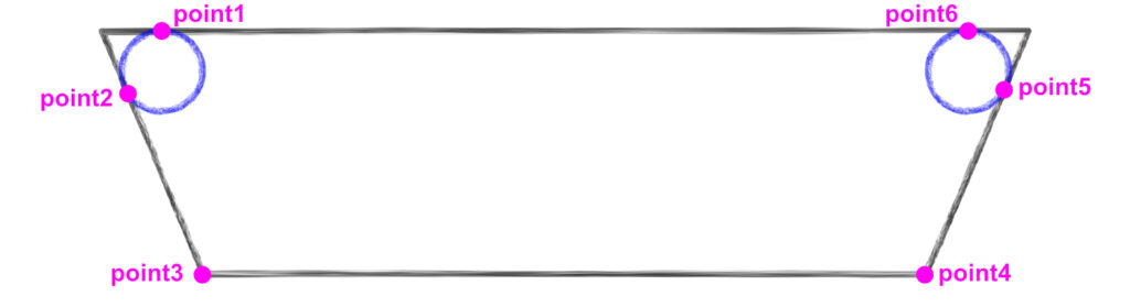
The above image shows the 6 points we’ll need to specify in OpenSCAD. We’ve already calculated point1 and point2. We can use the values we’ve calculated to find the other points.
- For
point3, thexvalue is equal to thex_offsetvalue, and theyvalue is0. - For
point4, thexvalue is equal to the specifiedwidthminus thex_offsetvalue. Theyvalue is also equal to0. - For
point5, thexvalue is equal to the specifiedwidthminus thebvalue. Theyvalue is equal to the specifiedheightminus theavalue. - For
point6, thexvalue is equal to the specifiedwidthminus thecvalue, and theyvalue is equal to the specifiedheight.
Adding those into our module looks like this:
module PuzzlePieceConnector(width, height, corner_radius) {
    x_offset = (width * 0.25) / 2;
    theta = atan(height / x_offset);
    c = corner_radius / tan(theta / 2);
    a = c * cos(90 - theta);
    b = c * sin(90 - theta);
    polygon(points = [
        [c, height],
        [b, height - a],
        [x_offset, 0],
        [width - x_offset, 0],
        [width - b, height - a],
        [width - c, height]
    ]);
}

// This variable tells OpenSCAD how "smooth" curves should be when rendering.
$fn=30;

// Render the module in OpenSCAD
PuzzlePieceConnector(50, 15, 2);
That last line renders out the module in OpenSCAD with a width of 50, height of 15, and corner radius of 2. This should give use the polygon we sketched out (without the rounded corners):
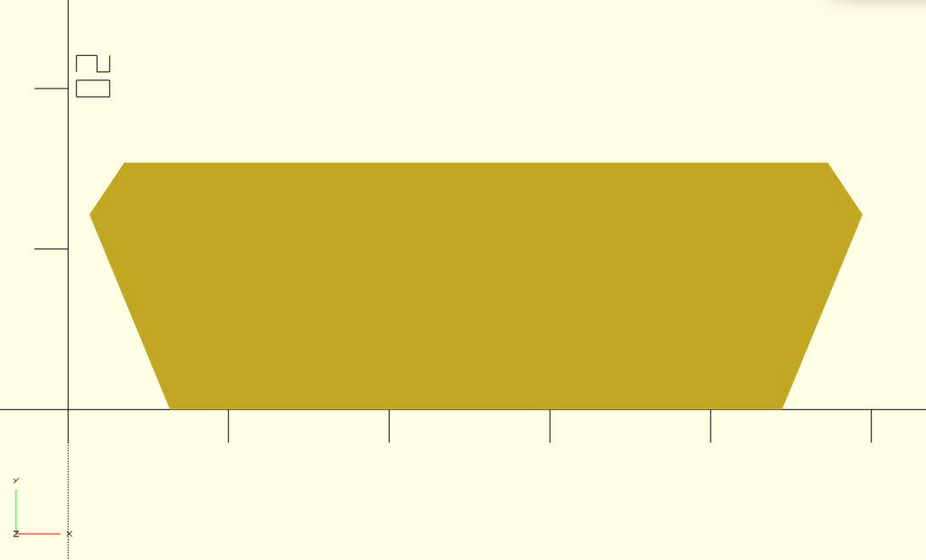
Perfect. Now all we need is to draw the circles for the rounded edges and combine it with this polygon.
Placing The Circles
Let’s look back at our zoomed in diagram:
We need to figure out the x and y coordinates for the center of the circles. For the left circle, we can see that the center is at the point (c, height - corner_radius).
The right circle is similar, but the x value will be equal to the width minus c, so (width - c, height - corner_radius).
In OpenSCAD, we’ll use the translate helper to move our circles into place:
module PuzzlePieceConnector(width, height, corner_radius) {
    x_offset = (width * 0.25) / 2;
    theta = atan(height / x_offset);
    c = corner_radius / tan(theta / 2);
    a = c * cos(90 - theta);
    b = c * sin(90 - theta);
    polygon(points = [
        [c, height],
        [b, height - a],
        [x_offset, 0],
        [width - x_offset, 0],
        [width - b, height - a],
        [width - c, height]
    ]);
    translate([c, height - corner_radius]) {
        circle(corner_radius);
    }
    translate([width - c, height - corner_radius]) {
        circle(corner_radius);
    }
}

// This variable tells OpenSCAD how "smooth" curves should be when rendering.
$fn=30;

PuzzlePieceConnector(50.8, 15.4, 2.35);
Let’s see how that looks rendered in OpenSCAD (note, I’ve added color to the circles to better see their placement):
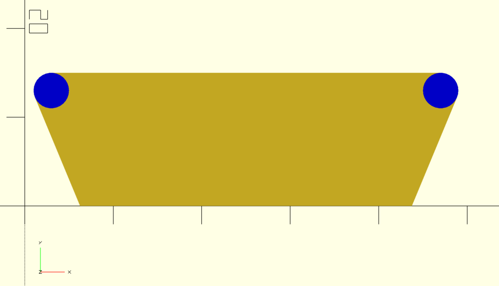
We’re looking good! The final step is to use the union() helper in OpenSCAD to combine all three components into a single, solid shape:
module PuzzlePieceConnector(width, height, corner_radius) {
    x_offset = (width * 0.25) / 2;
    theta = atan(height / x_offset);
    c = corner_radius / tan(theta / 2);
    a = c * cos(90 - theta);
    b = c * sin(90 - theta);
    union() {
        polygon(points = [
            [c, height],
            [b, height - a],
            [x_offset, 0],
            [width - x_offset, 0],
            [width - b, height - a],
            [width - c, height]
        ]);
        translate([c, height - corner_radius]) {
            circle(corner_radius);
        }
        translate([width - c, height - corner_radius]) {
            circle(corner_radius);
        }
    }
}

// This variable tells OpenSCAD how "smooth" curves should be when rendering.
$fn=30;

PuzzlePieceConnector(50, 15, 2);
Which renders into our final shape:
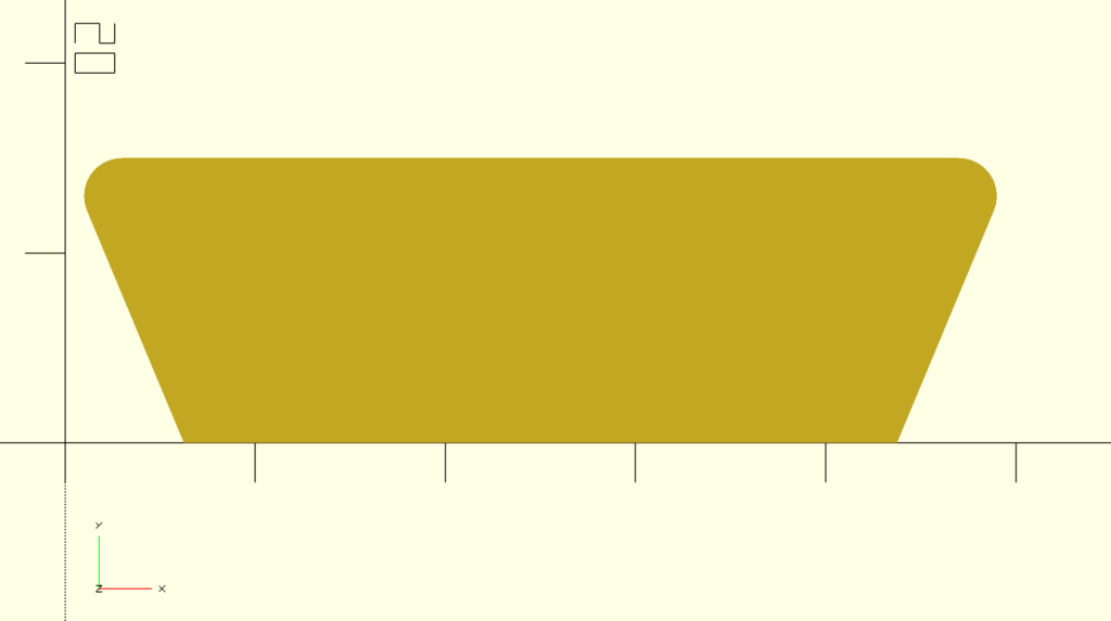
What’s great is we can also toggle the three variables to change how the piece is rendered.
PuzzlePieceConnector(40, 15, 5);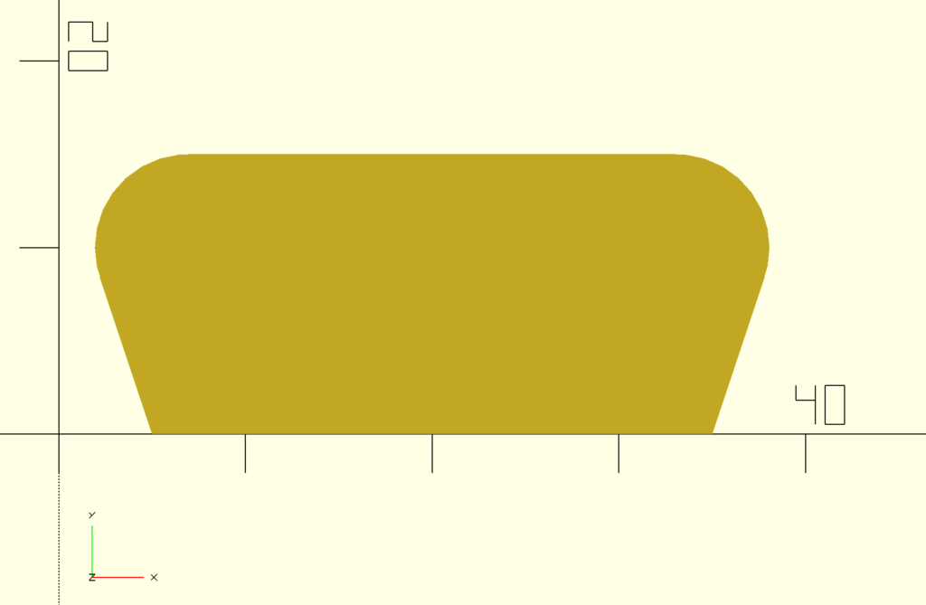
With this puzzle piece, I was able to add it to other pieces with union() (to create a male section) or difference() (to create a female section) like below:

Future Improvements
There’s definitely some improvements that can be made here. For example, if the corner_radius value is sufficiently large to the point where it exceeds the height of or width of the piece, the rendered shape starts becoming weird. We could probably calculate what the max value of corner_radius can be based off the height and width values and override the corner_radius value if it exceeds that limit.
Also there might be a few people who noticed that the specified “width” is not actually the width of the final piece. The width was actually the width of the original trapezoid, but then we “cut” its corners off which technically made it a bit smaller than the specified width. We could do some extra math to ensure the resulting piece is exactly the specified width, but for the purposes of my piñata that accuracy was not needed.
With all of this, I was able to break up my larger cardboard pieces and join them after they were cut out. It was all worth it, as my son loved his BlippiMobile piñata.